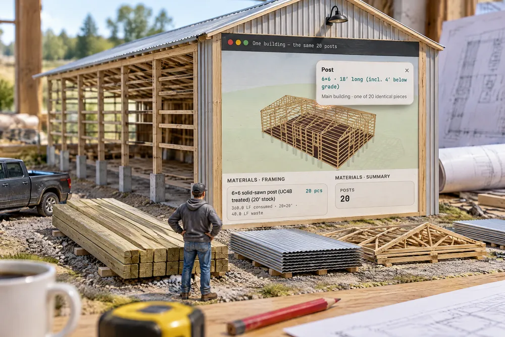
The picture and the numbers come from one building

The 3D view and the material list read the same pieces, so what you see and what you order cannot disagree.

The operating system built exclusively for post-frame and barndominium builders.

The short answer

Why should post frame design and estimating software use one model for both?

Because a drawing and a material list worked out separately agree only until someone changes the building. In post frame design and estimating software built on one model, every post, girt, purlin, truss chord and panel is placed once; the 3D view draws that list and the material list measures it, so what you see and what you order cannot disagree.

Why it works
  • Re-keying between disconnected tools is a measured cost. A NIST study estimated inadequate interoperability cost the US capital facilities industry $15.8 billion a year, including manual re-entry of data between systems. That is commercial and industrial work, but the mechanism is the same on a pole barn. NIST (Gallaher et al.), 2004 ↗
  • Disconnected tools mean hand transfers: in an industry survey skewed to firms with 50 or more staff, 49% of firms said they move data by hand when their apps don't connect. JBKnowledge ConTech Report, 2020 ↗
  • A short order costs the crew's day. Hansen gives buyers 48 hours to report shortages and warns that pieces found missing later are bought at full retail while the crew stands around with the time clock running. Hansen Pole Buildings, 2026 ↗
What it is

There is one building behind everything — the post-frame & barndominium operating system keeps one record of it, not a drawing in one place and a spreadsheet in another. Every post, girt, purlin, chord, header and panel is placed once. The 3D view draws that list. The material list measures that same list. The card that names a piece when you click it reads that same list. There is no second spreadsheet anywhere — stud walls, slab brackets, sleeves and the floor under a second storey are counted off the same pieces the 3D view draws.

Also called: single source of truth · model-driven takeoff · no drift between drawing and BOM

See it, piece by piece
01

The picture and the order are the same list of parts

One pass places every piece — post, girt, purlin, chord, header and panel. The 3D view draws that list. The material list measures that same list. The card that names a piece when you click it reads that same list. Click a post on the 40×60 and it says one of 20 identical pieces; the takeoff orders 20; the summary tile says Posts 20. There is no second spreadsheet, so the drawing cannot say one thing and the order another.
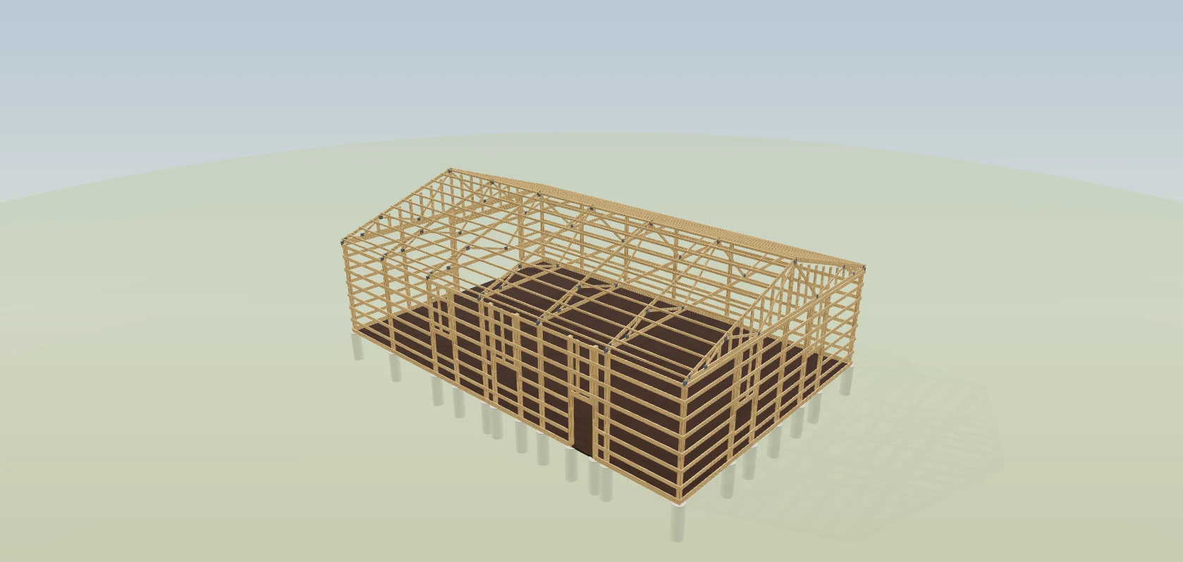
One building — the same posts, three ways
Post✕
6×6 · 18′ long (incl. 4′ below grade)
Main building · one of 17 identical pieces
UC4B ground-contact treated below grade
Materials · Framing
6x6 solid-sawn post (UC4B treated) (18′ stock)
378 LF consumed · 21×18′ · 0 LF waste · incl. 4′ embedment
21 pcs
6x6 jamb post (UC4B treated) (18′ stock)
36 LF consumed · 2×18′ · 0 LF waste
2 pcs
Materials · Summary
Posts
23
The same 20 posts three ways: the piece card, the takeoff line, the summary tile. Real screen · sample data.
Without it

The drawing and the material list are worked out two ways, agree until the building changes, and then nobody can tell which one is wrong.

Why we built it

The estimator orders straight off the model and the office stops reconciling a drawing against a spreadsheet. When every view reads the same parts, there is no second number to go wrong.

Sound familiar?“the drawing says one thing and the material list says another”
02

Quantities are measured off the drawing, not off a formula

Wall steel is counted per wall at that wall's own height — the high wall of a single slope, the field above a wainscot band, the gable triangle as a triangle — rather than one eave-height run around the perimeter. That is the difference between a number that is right on a rectangle and a number that is right on the building you drew.

Materials
Framing
6x6 solid-sawn post (UC4B treated) (18′ stock)
378 LF consumed · 21×18′ · 0 LF waste · incl. 4′ embedment — UC4B ground-contact treatment is a hard spec for embedded posts
21 pcs
6x6 jamb post (UC4B treated) (18′ stock)
36 LF consumed · 2×18′ · 0 LF waste · 2 laminated 2-ply (span > 9′) — full height, header load path
2 pcs
Nailed jamb (2-ply 2x6 / 4x6) (14′ stock)
134 LF consumed · 10×14′ · 6 LF waste · 8 doubled 2x6 + 2 4x6 — bearing on the splash plank, tied to the header. No embedment, no ground-contact treatment.
10 pcs
2x6 cripple (above headers) (8′ stock)
235.5 LF consumed · 30×8′ · 4.5 LF waste
30 pcs
2x8 door jamb + head jamb (overhead doors) (14′ stock)
39.6 LF consumed · 3×14′ · 2.4 LF waste
3 pcs
2x10 spring anchor pad (SYP #2 or better — NOT SPF) (8′ stock)
2 LF consumed · 1×8′ · 6 LF waste · lagged, never nailed — 4 × 3/8″ × 4″ lags, one near each corner
1 pcs
2x6 wall girt (cut-to-stock)
1240.8 LF consumed · 38×10′ + 116×8′ · 67.2 LF waste
154 pcs
2x8 skirt board (treated) (cut-to-stock)
180.9 LF consumed · 6×10′ + 17×8′ · 15.1 LF waste
23 pcs
2x6 eave strut (cut-to-stock)
200.5 LF consumed · 8×10′ + 16×8′ · 7.5 LF waste
24 pcs
2x4 roof purlin (cut-to-stock)
1447.7 LF consumed · 72×20′ + 24×8′ · 184.3 LF waste
96 pcs
1-ply 2x8 opening header (8′ stock)
22.2 LF consumed · 5×8′ · 17.8 LF waste
5 pcs
2-ply 2x12 opening header (16′ stock)
31.7 LF consumed · 2×16′ · 0.3 LF waste
2 pcs
2x6 window sill (8′ stock)
20.4 LF consumed · 4×8′ · 11.6 LF waste
4 pcs
Truss C40P4 (40′ span, 4/12)
spec-string per SmartBuild convention (C{span}P{pitch}); 4′ o.c. — 2 gable + 14 common · double-Fink (WW) webs, plated both faces (ANSI/TPI 1)
16 pcs
2-ply SYP 2x12 truss carrier (cut-to-stock)
240 LF consumed · 12×16′ + 4×12′ · 0 LF waste · 2-ply, both sidewalls — trusses at 4′ o.c. land between posts at 8′, so they bear on a carrier rather than on the post tops
16 pcs
2x4 bottom-chord bracing (16′ stock)
336 LF consumed · 21×16′ · 0 LF waste · {floor sq ft} × 0.00875 over 2400 sq ft — shop rule, not an engineered layout
21 pcs
2x4 miscellaneous bracing (20′ stock)
378 LF consumed · 21×20′ · 42 LF waste · {floor sq ft} × 0.00875 over 2400 sq ft — shop rule
21 pcs
2x4 X-bracing (20′ stock)
162 LF consumed · 9×20′ · 18 LF waste · {floor sq ft} × 0.0035 — only fires at or above 578 sq ft, as the shop rule does
9 pcs
2x6 corner bracing (20′ stock)
400 LF consumed · 20×20′ · 0 LF waste · flat 20 pieces — the shop's standing corner-bracing allowance
20 pcs
2x6 eave sub-fascia (cut-to-stock)
123.9 LF consumed · 6×16′ + 2×14′ · 0.1 LF waste · carries the eave fascia and the soffit's outer edge
8 pcs
2x6 rake sub-fascia (cut-to-stock)
92.2 LF consumed · 4×16′ + 4×8′ · 3.8 LF waste · carries the rake fascia at the gable overhang
8 pcs
Sheathing
Ribbed steel (exposed fastener) roof panel, 22.1′ length
2 rectangle face(s) @ 36″ coverage · 2745 sq ft (MBCI MasterRib (36″ coverage, ¾″ ribs @ 9″))
42 panels
Roof underlayment / condensation barrier
2745 sq ft + 10% lap
3,020 sqft
Wall steel panel, 11′ length
1851 sq ft net of openings @ 3′ coverage
61 panels
Wall steel panel, 7.4′ length
119 sq ft net of openings @ 3′ coverage
8 panels
Wall steel panel, 7.2′ length
22 sq ft net of openings @ 3′ coverage
1 panels
Wall steel panel, 1.9′ length
27 sq ft net of openings @ 3′ coverage
5 panels
Wall steel panel, 0.6′ length
9 sq ft net of openings @ 3′ coverage
8 panels
Wainscot panel, 3′ height
553 sq ft
69 panels
Wainscot panel, 0.1′ height
1 sq ft
6 panels
Gable-end wall steel (cut to rake)
267 sq ft of gable endwall infill — not a rectangle
27 panels
House wrap — 10′ roll (wall)
2295 sq ft of wall ÷ 211 sq ft per roll (empirical coverage)
11 ea
House wrap — 10′ roll (roof)
2745 sq ft of roof ÷ 211 sq ft per roll (empirical coverage)
14 ea
Trim
Ridge cap
62.1 LF
Rake trim
92.2 LF
Eave trim
123.9 LF
Corner trim
55.9 LF
Door/window trim
127.4 LF
Eave fascia — 5½″ steel fascia/post trim
covers the sub-fascia; separate from the eave drip edge, which both exist on a finished eave
123.9 LF
Rake fascia — 5½″ steel fascia/post trim
the gable-end equivalent of the eave fascia
92.2 LF
Vented aluminium soffit (12″)
123.8 LF of eave soffit as drawn — rake soffit is not modelled yet and is NOT included
123.8 LF
Inside/outside closure strip
matches every eave run of exposed-fastener steel
123.9 LF
Doors & Windows
Garage Door 14′ × 12′
1 ea
Walk-in Door 3′ × 6′-8″
1 ea
Window 4′ × 3′
4 ea
Fasteners
Truss plate (gang-nail, 20 ga galvanized)
pressed into both faces at each truss joint — the connection, not overlapping wood
384 ea
Truss/rafter-to-post uplift tie (H2.5A-class, 18 ga galvanized)
one per truss bearing per post line — uplift path from roof to column
32 ea
1½″ HH panel screw (color-matched)
{sf}×1.8 over 5594 sq ft — platform default; calibrate per builder
10,069 ea
Foundation
Concrete, 18″ dia × 4′ post holes
23 holes — uplift anchorage required on every embedded post
6 yd3
Footing pads, 18″ dia × 6″ concrete
bear below the frost line on undisturbed soil — 2000 psf presumptive bearing; precast "cookie" or poured in the hole
23 ea
Uplift restraint — full-depth concrete collar (as drawn)
the poured backfill above is the restraint; treated blocks bolted to the embedded face are the soil-backfill alternative
23 ea

Design aid, not engineering — this is a purchase-vs-consumed takeoff from the same members the model draws. Stock lengths are yard lengths (no 60′ 2x4s). Factory trusses stay factory trusses. Not a substitute for a licensed design professional, a stamped truss package, or your local building department.

The Sheathing lines: wall steel at its own run height, the wainscot band, and the gable end counted as a triangle. Real screen · sample data.
Without it

Wall steel counted as one eave-height lap around the perimeter quietly under-orders every single-slope and every wainscotted wall.

Why we built it

The yard delivers the steel the building needs, not the steel a rectangle would need. A formula is right on a simple box; measuring the drawn walls is right on the building you sold.

03

Click any stick and it tells you what it is

Try it

A jamb post reads 6×6 · 18′ long (incl. 4′ below grade) · Garage Door 1 · one of 8 identical pieces. A truss chord tells you it arrives inside one plated truss, not as a yard stick. A girt tells you it is face-nailed, one piece per bay. The count on the card is the quantity on the order, because both read the same record.

Inspect piece card
Wall girt
2×6 · 7′8″ long
Main building · one of 28 identical pieces
face-nailed to the posts; one piece per bay — it does not run through the column
Engineer requiredPost-frame posts, girts and their footings are designed by an engineer (NFBA guide specification; IRC R301.1.3). Why?
1 check · 1 note
Click any piece of the frame and it says what it is, its size, and how many of it there are. Real screen · sample data.
Without it

Somebody asks what a piece is or how many there are, and the answer means digging through a spreadsheet that may not match the drawing.

Why we built it

A new estimator learns post-frame by clicking the building, and an experienced one settles an argument in one click. The count on the card and the count on the order are the same number, so there is nothing to cross-check.

Sound familiar?“we ordered off the plan and were short”
04

Eave and ridge mean what the truss plant means

Dimensions follow the industry standard by default: eave, rake and ridge to the top of the purlins, width and length outside-of-girt to outside-of-girt. If your drawing set speaks to truss bearing and the post line, switch the convention and the numbers relabel without the building changing shape. Get this wrong and every elevation you hand a supplier is off by inches.

Design — Building
Wind and snow aren’t set. Spans and uplift use IRC tables only after you set them.Set them
BuildingHide
Dimension standardS618
Industry standard (ANSI/ASABE S618)

Eave, rake and ridge measured to the TOP OF THE PURLINS; width and length measured OUTSIDE-OF-GIRT to OUTSIDE-OF-GIRT. Switching restates the numbers — the building itself doesn’t move.

Width(ft)
−40′+
Length(ft)
−60′+
Eave height(ft)
−14′+
Lock eave
Bay spacing(ft)
−8′+
Truss spacing(ft)
−4′+
Girt spacing(ft)
−2′+
Purlin spacing(ft)
−2′+
Post embedment(ft)
−4′+

16 trusses at 4′ (60′ ÷ 4′ + 1)

WainscotOn
Height(ft)
−3′+
Colors

Walls · Trim · Wainscot · Framing wood

The dimension standard, with what eave, rake, width and length are measured to. Real screen · sample data.
Without it

Two builders quote the same 40×60 and mean different buildings, because one measures to the outside of the girt and the other to the post line.

Why we built it

The truss plant and the supplier read your numbers the way you meant them. A standard you can name is a standard you can defend.

Sound familiar?“3D render is just marketing, the real numbers are in a spreadsheet”
05

The geometry is checked automatically, not by looking at it

Every change to the engine is run against a standing suite of buildings before it ships: joints are cut and nothing pokes out through the steel, no member floats in mid-air, every opening frames legally, and every quantity is checked against the price book for a unit that matches. A broken shape fails a check here instead of turning up in a drawing you already emailed.

Without it

A design tool that is only checked by eye ships the occasional floating board or wrong count, and the builder finds it in front of a customer.

Why we built it

Builders trust a tool that does not break their buildings when it gets updated. Checking the geometry automatically is the only way a model this detailed stays right as it grows.

How it works
  1. 1The building is worked out once: every post, girt, purlin, chord, header and panel gets a position, a size, a trade name and a cut length.
  2. 2The 3D view draws that list and nothing else.
  3. 3The material list measures that same list into order lines, grouped by the industry's own names.
  4. 4Click a piece and it is named off that same record, in trade language.
  5. 5The geometry is checked automatically, with no 3D display attached, so a broken shape fails before it reaches a drawing.
Why we built it

When the drawing and the quantities are worked out two different ways, they agree until somebody changes the building — and then nobody can tell which one is wrong. Every quantity here is measured off the geometry that was actually drawn. That is why wall steel is counted per wall and per gable triangle rather than as one eave-height lap around the perimeter, which quietly under-counts every single-slope and every wainscotted wall.

The problem
  • A separate quantity formula silently diverges from the drawing after a geometry change.
  • A visual-only 3D tool cannot be trusted to order from.
What you get
Any geometry fix improves the order at the same time.
The engine is testable headlessly, so geometry regressions are caught before a screenshot.
The 3D layer is replaceable without touching a single material calculation.
What's inside
Industry-standard dimensions (ANSI/ASABE S618)

Every saved design carries which convention it is in. The industry standard measures eave, rake and ridge to the top of the purlins, and width and length outside-of-girt to outside-of-girt. The other option measures to truss bearing and the post line. A stored number is never quietly reinterpreted.
3D BUILDING DESIGNER

See the picture and the numbers come from one building
on one of your own jobs.

Thirty minutes with Keith — your building, your numbers. Bring the job where “the drawing says one thing and the material list says another” — we will show you exactly where that stops.

leads2build.com
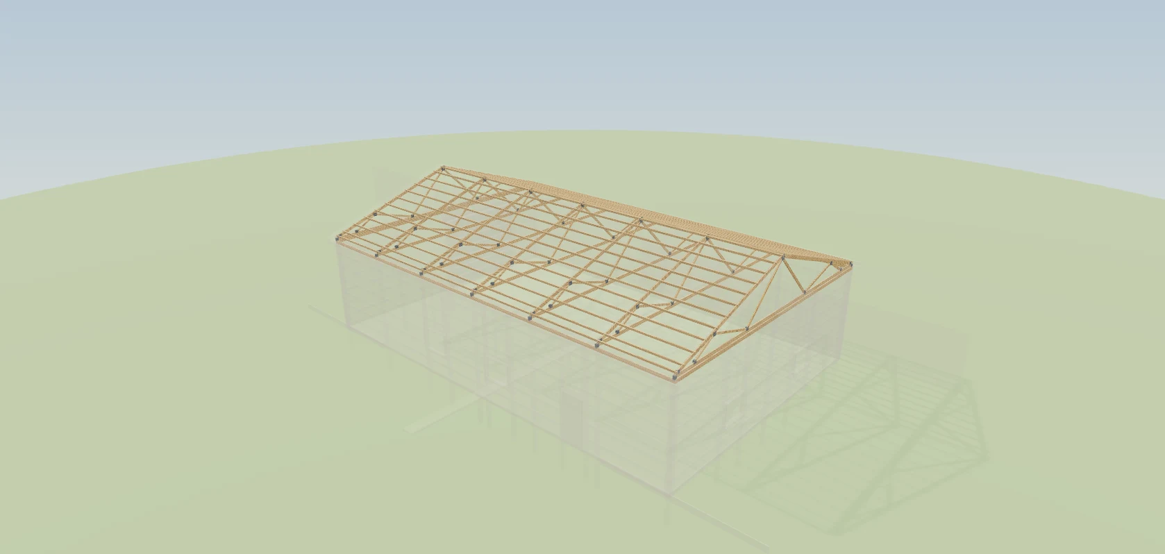
Trusses and purlins in the 3D designer
One building — the same posts, three ways
Post✕
6×6 · 18′ long (incl. 4′ below grade)
Main building · one of 17 identical pieces
UC4B ground-contact treated below grade
Materials · Framing
6x6 solid-sawn post (UC4B treated) (18′ stock)
378 LF consumed · 21×18′ · 0 LF waste · incl. 4′ embedment
21 pcs
6x6 jamb post (UC4B treated) (18′ stock)
36 LF consumed · 2×18′ · 0 LF waste
2 pcs
Materials · Summary
Posts
23